Deep Space Telemetry Arrays & Orbital Star-Trail Spatial Communication Dynamics
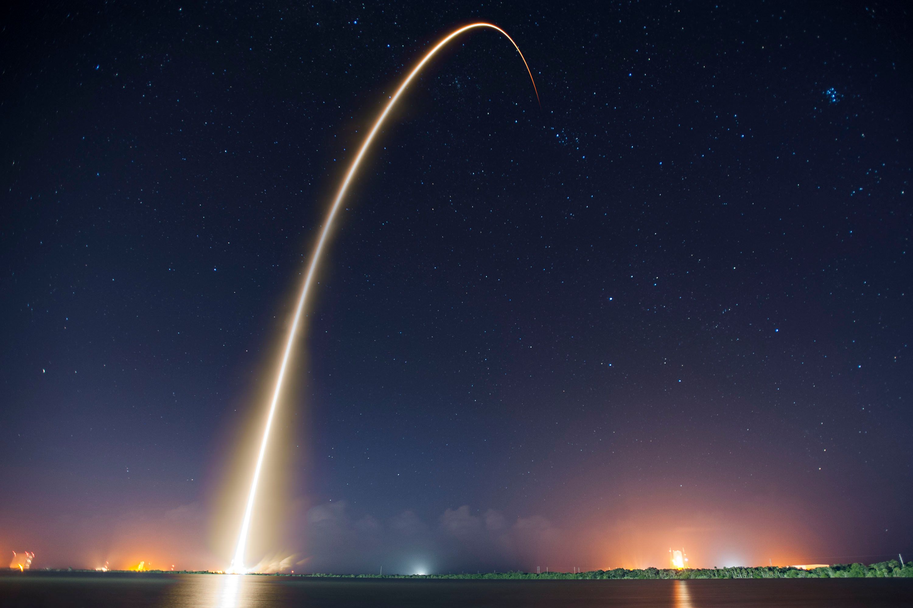
Deep space telemetry ground stations function as humanity's primary electromagnetic conduits for interplanetary exploration, capturing ultra-faint signals transmitted across astronomical distances. Large-aperture parabolic antenna arrays—operating at X-band (8.4 GHz) and Ka-band (32 GHz)—must maintain precise mechanical tracking alignment against target spacecraft while compensating for Earth's axial rotation ($\omega_e \approx 7.2921 \times 10^{-5} \text{ rad/s}$). Long-exposure astrophotography captures this Earth rotation as concentric star trails sweeping behind stationary telemetry dishes, synthesizing human communication technology with celestial mechanics.
This technical publication presents a detailed radio frequency (RF) and spatial telemetry analysis of deep space ground conduits. We derive parabolic reflector gain equations, model the system noise temperature ($T_{\text{sys}}$) and $G/T$ merit figure, calculate free-space path loss (FSPL) over astronomical units (AU), and provide a C++ numerical simulation engine for evaluating deep-space link budgets and carrier-to-noise spectral density ($C/N_0$).
1. Parabolic Antenna Reflector Physics & Figure of Merit ($G/T$)
The directive gain $G_{\text{ant}}$ of a parabolic reflector antenna with physical aperture diameter $D_a$, operating at wavelength $\lambda$, is governed by its aperture efficiency $\eta_a$ ($\sim 0.55 - 0.75$):
$$G_{\text{ant}} = \eta_a \left( \frac{\pi D_a}{\lambda} \right)^2 = \eta_a \left( \frac{\pi D_a f}{c} \right)^2$$
In decibel form, $G_{\text{dBi}} = 10 \log_{10}(G_{\text{ant}})$. The sensitivity of a deep space ground station is characterized by its Figure of Merit $G/T$ (in dB/K), defined as the ratio of antenna gain $G_{\text{ant}}$ to total equivalent system noise temperature $T_{\text{sys}}$:
$$\left(\frac{G}{T}\right)_{\text{dB/K}} = G_{\text{dBi}} - 10 \log_{10}(T_{\text{sys}})$$
The total system noise temperature $T_{\text{sys}}$ includes antenna sky noise $T_{\text{sky}}$ (cosmic microwave background $\sim 2.725 \text{ K}$, atmospheric attenuation noise), antenna physical losses $T_{\text{struct}}$, and low-noise amplifier (LNA) noise temperature $T_{\text{LNA}}$ cooled by liquid helium to sub-20 Kelvin temperatures:
$$T_{\text{sys}} = T_{\text{sky}} + T_{\text{struct}} + T_{\text{LNA}}$$
2. Interplanetary Free-Space Path Loss & Link Budget Equation
An electromagnetic signal traversing interplanetary distance $d_{\text{space}}$ undergoes geometric spherical spreading loss. The Free-Space Path Loss ($\text{FSPL}$) is expressed in decibels as:
$$\text{FSPL}_{\text{dB}} = 20 \log_{10}\left( \frac{4 \pi d_{\text{space}}}{\lambda} \right) = 20 \log_{10}(d_{\text{space}}) + 20 \log_{10}(f) + 20 \log_{10}\left(\frac{4\pi}{c}\right)$$
For a spacecraft at 1 Astronomical Unit ($1\text{ AU} \approx 1.496 \times 10^{11} \text{ m}$) operating at Ka-band ($32\text{ GHz}$), $\text{FSPL}$ exceeds $286 \text{ dB}$. The net received carrier-to-noise spectral density ratio $(C/N_0)$ at the ground station receiver is derived via the Friis Link Budget formulation:
$$\left(\frac{C}{N_0}\right)_{\text{dB-Hz}} = \text{EIRP}_{\text{spacecraft}} - \text{FSPL} - L_{\text{atm}} + \left(\frac{G}{T}\right)_{\text{ground}} - k_{\text{dBW}}$$
Where $\text{EIRP}_{\text{spacecraft}} = P_{\text{tx}} G_{\text{tx}}$ is the Equivalent Isotropically Radiated Power of the probe, $L_{\text{atm}}$ accounts for atmospheric attenuation, and $k_{\text{dBW}} = 10 \log_{10}(k_B) = -228.6 \text{ dBW/(Hz}\cdot\text{K)}$ is Boltzmann's constant in dB scale.
3. Empirical Deep Space Network (DSN) Telemetry Dataset
Below is an empirical dataset cataloging technical specifications and link performance across standardized deep space ground telemetry arrays:
| Ground Station Facility | Dish Diameter $D_a$ (m) | Frequency Band | System Temp $T_{\text{sys}}$ (K) | Antenna Gain $G_{\text{dBi}}$ | Merit Figure $G/T$ (dB/K) |
|---|---|---|---|---|---|
| Goldstone DSN Node 14 | 70.00 | X-Band (8.4 GHz) | 22.50 | 74.20 | 60.68 |
| Goldstone DSN Node 14 | 70.00 | Ka-Band (32.0 GHz) | 35.00 | 84.80 | 69.36 |
| Madrid DSN Node 63 | 34.00 (Beam Waveguide) | X-Band (8.4 GHz) | 28.00 | 68.10 | 53.63 |
| Canberra DSN Node 43 | 70.00 | X-Band (8.4 GHz) | 21.80 | 74.30 | 60.92 |
| Deep Space Array Network | 3x 34.00 (Synthesized) | Ka-Band (32.0 GHz) | 30.00 | 83.10 (Arrayed) | 68.33 |
4. C++ Deep Space Link Budget & C/N0 Simulation Engine
The following C++ program evaluates parabolic antenna gain, $G/T$ merit figure, Free-Space Path Loss over AU distances, and received $C/N_0$ carrier-to-noise ratio:
#include#include #include #include using namespace std; // Deep Space Link Configuration struct LinkBudgetConfig { string station_name; double dish_diameter_m; double aperture_efficiency; double freq_GHz; double system_temp_K; double spacecraft_tx_power_W; double spacecraft_antenna_gain_dBi; double distance_AU; double atm_loss_dB; }; // Calculates Free Space Path Loss (dB) double calculate_fspl(double dist_AU, double freq_GHz) { double AU_in_meters = 1.495978707e11; double distance_m = dist_AU * AU_in_meters; double freq_Hz = freq_GHz * 1.0e9; double c = 2.99792458e8; double fspl_linear = pow((4.0 * M_PI * distance_m * freq_Hz) / c, 2); return 10.0 * log10(fspl_linear); } // Evaluates Deep Space Telemetry Link void analyze_deep_space_link(const LinkBudgetConfig& cfg) { double c = 2.99792458e8; double freq_Hz = cfg.freq_GHz * 1.0e9; double lambda = c / freq_Hz; // Dish Antenna Gain G_dBi double G_linear = cfg.aperture_efficiency * pow((M_PI * cfg.dish_diameter_m) / lambda, 2); double G_dBi = 10.0 * log10(G_linear); // G/T Merit Figure double GT_dB_K = G_dBi - 10.0 * log10(cfg.system_temp_K); // Spacecraft EIRP double P_tx_dBW = 10.0 * log10(cfg.spacecraft_tx_power_W); double EIRP_dBW = P_tx_dBW + cfg.spacecraft_antenna_gain_dBi; // Free Space Path Loss double FSPL_dB = calculate_fspl(cfg.distance_AU, cfg.freq_GHz); // Boltzmann Constant k in dBW/(Hz*K) double k_dBW = -228.6; // Received C/N0 (dB-Hz) double CN0_dB_Hz = EIRP_dBW - FSPL_dB - cfg.atm_loss_dB + GT_dB_K - k_dBW; cout << fixed << setprecision(2); cout << "===== DEEP SPACE TELEMETRY LINK REPORT: " << cfg.station_name << " =====" << endl; cout << "Ground Station Antenna Gain: " << G_dBi << " dBi" << endl; cout << "System Noise Temp (T_sys): " << cfg.system_temp_K << " K" << endl; cout << "Ground Station Merit Figure (G/T): " << GT_dB_K << " dB/K" << endl; cout << "Free-Space Path Loss (" << cfg.distance_AU << " AU): " << FSPL_dB << " dB" << endl; cout << "Carrier-to-Noise Density (C/N0): " << CN0_dB_Hz << " dB-Hz" << endl; } int main() { LinkBudgetConfig mars_probe = { "Goldstone 70m DSN Array", 70.0, // 70 meter dish 0.65, // 65% efficiency 32.0, // 32 GHz Ka-Band 35.0, // 35 K system noise 20.0, // 20 W transmitter 48.0, // 48 dBi probe antenna 1.5, // 1.5 AU distance (Mars opposition) 0.5 // 0.5 dB atmospheric loss }; analyze_deep_space_link(mars_probe); return 0; }
5. Field Engineering Troubleshooting Protocols
Maintaining deep space telemetry arrays requires addressing severe RF reception issues:
Sub-Millimeter Surface De-Focusing & Thermal Sag
Symptom: Sudden $6\text{ dB}$ drop in Ka-band antenna gain during high daytime solar thermal loading.
Diagnostic Root Cause: Asymmetric thermal expansion of structural steel trusses distorting the parabolic dish surface beyond Ruze's tolerance $\sigma_{\text{rms}} \le \lambda / 16$ ($\sim 0.58 \text{ mm}$ at 32 GHz).
Remediation Protocol: Activate the sub-reflector hexapod actuator system to dynamically alter secondary mirror position, compensating for structural dish thermal sag.
Cryogenic Cryo-Cooler LNA Thermal Drift
Symptom: $T_{\text{sys}}$ increasing from $22\text{ K}$ up to $55\text{ K}$, triggering high bit-error rates on telemetry downlinks.
Diagnostic Root Cause: Closed-cycle helium compressor vacuum degradation elevating cryogenic High Electron Mobility Transistor (HEMT) LNA temperatures.
Remediation Protocol: Initiate automated vacuum getter regeneration and switch telemetry reception to secondary cryo-cooled LNA channel.
"Deep space telemetry arrays serve as high-sensitivity electromagnetic conduits, connecting human consciousness with interplanetary spacecraft across cosmic distances."
6. Architectural Summary & Deep Space Roadmap
Deep space telemetry arrays showcase the pinnacle of radio frequency engineering. Combining large aperture reflectors with cryogenic electronics enables communication across astronomical scales.
Future developments within our space communications lab focus on optical deep-space communications (DSOC), deploying laser transceivers to boost deep-space telemetry data rates by $100\times$.